
Sunday 3-730 and Monday 2-630 and Tuesday 2-330 (meeting with Matt)
Nikki and I started running through Matt's projection exercise instructions. Took a little time to set up projector, duck, ball etc. then mostly worked on painting dots and stripes onto the environment. Painting on the objects can be very disorienting. The ground plane is closest to perp. with the projector so small adjustments make for big results. Same goes for the edges of the sphere and duck, when you get to the boarder of what the projector sees the images become more skewed.
After continuing to draw on Monday, I decided to start setting up our Maya scene for projection. I took rough estimates of distances for now until we are done with the photo shop phase and can touch and move the objects to get better measurements. Part one of the 3d experiments is going to be a problem. I'm supposed to apply a texture with a series of spheres all of the same size cover the objects. I cant properly project/edit uv's to give a uniformed pattern. The other two steps, animating lights/shadows and "intrusion"/extrusion are blocked and ready to go.
Monday, December 13, 2010
Adventures in Camoland
I made contributions in several areas for this project beside conceptual development. I was in charge of building, lighting, texturing, animating and rendering the environments that were to be projected. Jon helped me out a lot with the rendering on the render farm. I was the only one in the group with projection mapping experience (to start of with anyway) so getting the physical spaces to match the virtual was my job. Also I worked with Ben to calculate specs. on the Sanyo projector (we already had numbers for the cannon) so that we could align it correctly in the physical space as well as properly replicating the virtual world to match the physical. Jon and I spent a lot of time exploring how to project onto 3 faces of a geometrical object from a projector location distant from the audiences point of view. I also set up, lit and shot (along wit Jon) the EMMA space for green screening as well as post production work to combine the footage and our animation. Jon and I also spent time in post doing audio and timing our animations to align with actor performances.
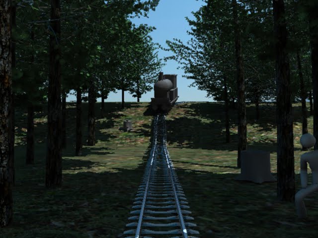
Alex, Jon and myself were assigned group one : camouflage training for this assignment. We wanted to treat the stage/props like a blank canvas. Something that we could paint with light and projection but keep a believable environment for the actors to perform in and with. Before meeting with the Ibsen, Tori, Alex, Aaron, and Ashley, we discussed several camouflage techniques and at some point found a period camouflage lookout that was shaped like a tree trunk. We decided to create a forest environment for out actors to perform in. Later we added a train and tracks to the piece as a starting point of action. It gave the actors a reason for being in the environment (sabotaging the train while going through a mock training session). The script changed very little from day one. The "classroom" scene was a little harder to figure out. We decided in the end to go with a bunker type setting so that when the forest turned into it we would keep continuity with "in the field training".
We found that when projecting onto 3 faces from a "non viewer" angle that no adjustments need to be made to projector configuration, but the process for rendering in maya does. As long as you pick a point of origin in the physical space and measure from there to your objects and projector (and matchin those measurements in maya) that projections would still align. The trouble came when trying to figure out how to compensate for the perspective difference from audience to a projector 16 feet of the ground.
We found that an extra camera was needed to correctly project from maya. We added a camera from the audiences point of view, or at least a rough estimate. We rendered from that camera, saved it as a texture material, and projected it back onto the objects from our "projector" camera. When viewed from the audience camera the texture should hypothetically create the illusion of forced perspective. I say hypothetically because properly projecting the textures is a lot harder than expected. I had to do a lot of UV tweaking. There must be a better way and definitely something we need to discover. I also learned that when rendering the texture for projection, using 2048x1536 resulted in a much higher quality render even though we rendered at 1024x768 in the end.
I wanted to create an environment that felt like more than just projections and to extend the space. I tossed out the idea of green screening one of the actors to insert them in the physical space and everyone was on board. Alex, Jon and I met over in EMMA where we set up the green screen and Alex gave us some instructions on how to light it. Later on that week we met with actress Tori, she volunteered for our experiment, to shoot the footage. When lighting the screen we basically just tried to flatten the background as much as possible and eliminate unwanted shadows. After shooting Jon and I brought the footage into After Effects where it was fairly simple to rough out the screen. We also got pretty lucky with how Tori fit into the digital space. Initially, she did not walk far enough to get to the train tracks, lucky for us we just moved them closer and it fit perfect. With a little color matching and use of a matte choker we had her in the virtual space and acting. In the end it probably gave the actors the most grief because they had to act with a video whom could not respond to and sometimes even see.
Our group put some real time in last weekend in order to pull the show together. Even though we had solidified ideas and environments, technical difficulties always slow you down. The following is Jons account of 9 hours of Friday activities.
Friday December 3 - attempted to align 3D projection maps to physical objects on stage (2
boxes), took measurements using measuring tape, dimensions of object, distance of object to
projector, height of projector relative to object, Jeremy used method from Camouflage Project
to align and project onto physical objects
- difficulty measuring the angle (vertical tilt) of the camera in the physical space, difficulty
measuring precise distances from object to camera and height of camera using measuring tape,
need a more precise tool or a more precise method to measure at these distances in complex
environments
- test object (larger box lying length wise, horizontally on the right side of stage), marked and in
its final position
- in Maya, test used cube with a simple red shader as the projected object, dimensions of
physical object and other measurements entered into Maya project
- difficulty aligning projected objects with physical objects using method from Camouflage
Project, projected objects weren't oriented properly, seemingly wrong angles and distance to
camera, vertical tilt of camera also seemed off
- test object moved in physical space so front face sat head on relative to camera view,
perpendicular to camera, instead of the angle set for final position, rotated against marked
focal point (lower left front facing corner of object), this was done in an attempt to ease the
process of alignment, object in Maya reconfigured accordingly
- new measurements taken, entered into Maya project
- fail, projection map still off, seemed to make no difference, speculated either the resolution,
aspect ratio, or some other lens setting of projector was to blame
- resolution of projector correct (1024 x 768), apparently the projector is supposed to auto
detect proper resolution and aspect ratio from computer at default, so default settings were
reapplied to projector
- fail, projection map still off, seemed to make no difference
- began deviating from exact measurements, tweaking numbers in an attempt to align
projected object, sporadic success, some changes got us closer to alignment while others undid
any perceivable progress, took 1 step forward and two steps back, at this point we may have
been going in circles
- contacted Ben for assistance, reverted to measurements and ran through the Camouflage
procedure again, still ran into a similar problem with alignment, proportions of projected object
seemed off, front face too large and top face too narrow
- made attempts to raise the height of the camera in Maya project and adjust the angle
(vertical tilt) accordingly, attempt to fix issue with front and top proportions
- mixed results, seemed as though every time an issue with front or top face was resolved
something else would fall out of alignment
- determined that the height of the camera relative to the distance from the focal point of
the object needed adjustment, as opposed to changing only the height of the camera then
adjusting the angle accordingly
- attempted to use focal point (lower left front facing corner of object), as a rotation point for
camera in Maya project, allowing us to adjust the "height of the camera relative to the distance
from the focal point of the object"
- success, but only to a certain extent, after about an hour of messing around with this method
we were able to achieve a nearly acceptable alignment, the problem involved the right side or
outer edge of the test object, it was skewed at an odd angle while every other edge was aligned
properly, inexplicable and couldn't be solved with the 'focal point rotation' method
- suspected that either the lens of the projector or the camera settings in Maya were to blame
- scheduled meeting with Ben around noon the next day
We gave up for the night after getting now where. After meeting with Ben the next day, we discovered that since our projector was hung upside down, we needed to flip our film offset to negative and like magic it aligned almost perfectly.
We spent the next 14 hours sat. building and lighting our finalized virtual sets.
Sunday we managed to spend 30+ hours in an attempt to wrap up by monday. We got everything but sound which Jon and I finished on Tuesday. Jon did most of it however, I was still out of it, but I was good backup.
Tree Textures


Textures Projected back onto geometry


Physical Objects Projected On

Wall Projections

FINAL FOREST

FINAL CLASS

Shots While Working and From Show
 Forest Performance
 Tori Green Screened
 Blank Canvas

Jon Enjoying the Green Screen

Projection Testing

I had a great group, Jon, Alex, Ibsen, Tori, Alex, Aaron, and Ashley.. We all worked together great and everyone was open to change and adaptation to make this project work. Lots of long hours paid off.
Alex, Jon and myself were assigned group one : camouflage training for this assignment. We wanted to treat the stage/props like a blank canvas. Something that we could paint with light and projection but keep a believable environment for the actors to perform in and with. Before meeting with the Ibsen, Tori, Alex, Aaron, and Ashley, we discussed several camouflage techniques and at some point found a period camouflage lookout that was shaped like a tree trunk. We decided to create a forest environment for out actors to perform in. Later we added a train and tracks to the piece as a starting point of action. It gave the actors a reason for being in the environment (sabotaging the train while going through a mock training session). The script changed very little from day one. The "classroom" scene was a little harder to figure out. We decided in the end to go with a bunker type setting so that when the forest turned into it we would keep continuity with "in the field training".
We found that when projecting onto 3 faces from a "non viewer" angle that no adjustments need to be made to projector configuration, but the process for rendering in maya does. As long as you pick a point of origin in the physical space and measure from there to your objects and projector (and matchin those measurements in maya) that projections would still align. The trouble came when trying to figure out how to compensate for the perspective difference from audience to a projector 16 feet of the ground.
We found that an extra camera was needed to correctly project from maya. We added a camera from the audiences point of view, or at least a rough estimate. We rendered from that camera, saved it as a texture material, and projected it back onto the objects from our "projector" camera. When viewed from the audience camera the texture should hypothetically create the illusion of forced perspective. I say hypothetically because properly projecting the textures is a lot harder than expected. I had to do a lot of UV tweaking. There must be a better way and definitely something we need to discover. I also learned that when rendering the texture for projection, using 2048x1536 resulted in a much higher quality render even though we rendered at 1024x768 in the end.
I wanted to create an environment that felt like more than just projections and to extend the space. I tossed out the idea of green screening one of the actors to insert them in the physical space and everyone was on board. Alex, Jon and I met over in EMMA where we set up the green screen and Alex gave us some instructions on how to light it. Later on that week we met with actress Tori, she volunteered for our experiment, to shoot the footage. When lighting the screen we basically just tried to flatten the background as much as possible and eliminate unwanted shadows. After shooting Jon and I brought the footage into After Effects where it was fairly simple to rough out the screen. We also got pretty lucky with how Tori fit into the digital space. Initially, she did not walk far enough to get to the train tracks, lucky for us we just moved them closer and it fit perfect. With a little color matching and use of a matte choker we had her in the virtual space and acting. In the end it probably gave the actors the most grief because they had to act with a video whom could not respond to and sometimes even see.
Our group put some real time in last weekend in order to pull the show together. Even though we had solidified ideas and environments, technical difficulties always slow you down. The following is Jons account of 9 hours of Friday activities.
Friday December 3 - attempted to align 3D projection maps to physical objects on stage (2
boxes), took measurements using measuring tape, dimensions of object, distance of object to
projector, height of projector relative to object, Jeremy used method from Camouflage Project
to align and project onto physical objects
- difficulty measuring the angle (vertical tilt) of the camera in the physical space, difficulty
measuring precise distances from object to camera and height of camera using measuring tape,
need a more precise tool or a more precise method to measure at these distances in complex
environments
- test object (larger box lying length wise, horizontally on the right side of stage), marked and in
its final position
- in Maya, test used cube with a simple red shader as the projected object, dimensions of
physical object and other measurements entered into Maya project
- difficulty aligning projected objects with physical objects using method from Camouflage
Project, projected objects weren't oriented properly, seemingly wrong angles and distance to
camera, vertical tilt of camera also seemed off
- test object moved in physical space so front face sat head on relative to camera view,
perpendicular to camera, instead of the angle set for final position, rotated against marked
focal point (lower left front facing corner of object), this was done in an attempt to ease the
process of alignment, object in Maya reconfigured accordingly
- new measurements taken, entered into Maya project
- fail, projection map still off, seemed to make no difference, speculated either the resolution,
aspect ratio, or some other lens setting of projector was to blame
- resolution of projector correct (1024 x 768), apparently the projector is supposed to auto
detect proper resolution and aspect ratio from computer at default, so default settings were
reapplied to projector
- fail, projection map still off, seemed to make no difference
- began deviating from exact measurements, tweaking numbers in an attempt to align
projected object, sporadic success, some changes got us closer to alignment while others undid
any perceivable progress, took 1 step forward and two steps back, at this point we may have
been going in circles
- contacted Ben for assistance, reverted to measurements and ran through the Camouflage
procedure again, still ran into a similar problem with alignment, proportions of projected object
seemed off, front face too large and top face too narrow
- made attempts to raise the height of the camera in Maya project and adjust the angle
(vertical tilt) accordingly, attempt to fix issue with front and top proportions
- mixed results, seemed as though every time an issue with front or top face was resolved
something else would fall out of alignment
- determined that the height of the camera relative to the distance from the focal point of
the object needed adjustment, as opposed to changing only the height of the camera then
adjusting the angle accordingly
- attempted to use focal point (lower left front facing corner of object), as a rotation point for
camera in Maya project, allowing us to adjust the "height of the camera relative to the distance
from the focal point of the object"
- success, but only to a certain extent, after about an hour of messing around with this method
we were able to achieve a nearly acceptable alignment, the problem involved the right side or
outer edge of the test object, it was skewed at an odd angle while every other edge was aligned
properly, inexplicable and couldn't be solved with the 'focal point rotation' method
- suspected that either the lens of the projector or the camera settings in Maya were to blame
- scheduled meeting with Ben around noon the next day
We gave up for the night after getting now where. After meeting with Ben the next day, we discovered that since our projector was hung upside down, we needed to flip our film offset to negative and like magic it aligned almost perfectly.
We spent the next 14 hours sat. building and lighting our finalized virtual sets.
Sunday we managed to spend 30+ hours in an attempt to wrap up by monday. We got everything but sound which Jon and I finished on Tuesday. Jon did most of it however, I was still out of it, but I was good backup.
Tree Textures


Textures Projected back onto geometry


Physical Objects Projected On

Wall Projections
EARLY
FINAL FOREST

FINAL CLASS

Shots While Working and From Show
Bunker/Class Performance
 Forest Performance
 Tori Green Screened
 Blank Canvas
Jon Enjoying the Green Screen

Projection Testing

I had a great group, Jon, Alex, Ibsen, Tori, Alex, Aaron, and Ashley.. We all worked together great and everyone was open to change and adaptation to make this project work. Lots of long hours paid off.
Tuesday, November 16, 2010
Process For Projecting on Cube in EMMA
Step by step process
A.)-For this first test the Audience's view wasn't taken into much consideration, but it should. (in order to view the projection correctly you need to be at projector level which in this case was lying on the floor.)
B.)-Our next step was to measure and arrange our objects in physical space.
1.The object we were projecting onto was a rectangular box that measured 77.75"x30"x18".
2.The projector was, in this case, arbitrarily placed 147.5 " away from the center front face of the box which was enough distance project on the entire surface. When considering projector placement it should in general be as Matt wrote- as close as practical for maximum resolution and minimum background bleed. I also tried to place it perpendicular to the box. At this stage it is also important to either zoom all the way in or all the way out so that calculations down the road are easier to find.

C.)Modeling a Virtual "set" that matched the Physical one.
1.I chose a global origin of 0,15,0 so that the box could be at the center of the virtual space with the bottom face flush with the ground plane (translate Y=15 since the box would be 30 units high)
2. It is important to also pick your units of measure within maya. We measure the physical in inches so chose inches for maya.
3.I built a polygonal cube that matched the measurements of the physical cube 77.75x30x18 and placed it at the origin. I left rotations at o,o,o since we would be projecting on the object perpendicular from one side only (in order to calibrate our maya camera with the projector we started simple with the hopes the same measurements would work when the objects are angled).
4. Next I created a camera within maya. Using the measuring tool I placed it 147.5" away from the front edge and center of the box.
5. After the camera positions match in physical and virtual space, we needed match the camera's attributes with those of the porjector.
-Aspect Ratio: 4:3- The easiest. The projector was set to 4:3 so we did the same for the camera.
-Field of View: 35.48: Can be found hopefully in the manual, or what we did was project a perfect square onto a perpindicular surface. Measure the length from lens to center of projection then from center to edge of projection we could figure out the angle using the Pythagorean theorem. Multiply by two since we only calulated half the field of view. I'm also pretty sure that the Aperture setting directly affects/calculates field of view so finding that in the manual would also be idea.
-Aperture: .902-.678: So we had a lot of trouble figuring this number out at first. Through some rough mathematics and some other measurements we got a projection that lined up closely. We later found out that some of the confusion lied in somewhat different understanding of what aperture meant in Maya compared to the Projector. It turns out that for a projector, aperture is reffering to the the LCD panel size, which according to some sources is the diagonal of the aperture measurements. Using the value from the manual produced bad results in Maya, as before, but produced better results once we realized we had been using the wrong end of the focal length range.(Hence why it is important to zoom all the way in or out in the beginning).

At this point, with all of our measurements and camera/projector settings matching in both maya and in EMMA, we were able project onto our cube properly without manual tweaking and the render-re-render process.
We did a quick experiment with rotating the physical box and then matching that rotation for the virtual to see if our calculations would still be effective and they were.
The animations were secondary for the most part. Just wanted to test what kind of depth you could get inside such a small space. I didn't push it to the max but I think it was pretty successful overall.


1.I chose a global origin of 0,15,0 so that the box could be at the center of the virtual space with the bottom face flush with the ground plane (translate Y=15 since the box would be 30 units high)
2. It is important to also pick your units of measure within maya. We measure the physical in inches so chose inches for maya.
3.I built a polygonal cube that matched the measurements of the physical cube 77.75x30x18 and placed it at the origin. I left rotations at o,o,o since we would be projecting on the object perpendicular from one side only (in order to calibrate our maya camera with the projector we started simple with the hopes the same measurements would work when the objects are angled).
4. Next I created a camera within maya. Using the measuring tool I placed it 147.5" away from the front edge and center of the box.
5. After the camera positions match in physical and virtual space, we needed match the camera's attributes with those of the porjector.
-Aspect Ratio: 4:3- The easiest. The projector was set to 4:3 so we did the same for the camera.
-Field of View: 35.48: Can be found hopefully in the manual, or what we did was project a perfect square onto a perpindicular surface. Measure the length from lens to center of projection then from center to edge of projection we could figure out the angle using the Pythagorean theorem. Multiply by two since we only calulated half the field of view. I'm also pretty sure that the Aperture setting directly affects/calculates field of view so finding that in the manual would also be idea.
-Aperture: .902-.678: So we had a lot of trouble figuring this number out at first. Through some rough mathematics and some other measurements we got a projection that lined up closely. We later found out that some of the confusion lied in somewhat different understanding of what aperture meant in Maya compared to the Projector. It turns out that for a projector, aperture is reffering to the the LCD panel size, which according to some sources is the diagonal of the aperture measurements. Using the value from the manual produced bad results in Maya, as before, but produced better results once we realized we had been using the wrong end of the focal length range.(Hence why it is important to zoom all the way in or out in the beginning).

We did a quick experiment with rotating the physical box and then matching that rotation for the virtual to see if our calculations would still be effective and they were.
The animations were secondary for the most part. Just wanted to test what kind of depth you could get inside such a small space. I didn't push it to the max but I think it was pretty successful overall.


Projection Mapping Second pass WIP
In recent years, the art of 3D projection mapping has been climbing in popularity. According to Wikipedia, 3D projection mapping is defined as “any method of mapping three-dimensional points to a two-dimensional plane.” The most common form of this technique is the mapping of geometrical shapes and architectural facades. These 3D projections give artists the power “change” the objects surface and create illusions of depth, forced perspective as well as more dramatic special effects such as objects crumbling, morphing and turning into cloth. However before these artistic visualizations can be realized, you must understand how the mapping process works and that is what I have been researching in recent weeks.
Initially my knowledge of the projection process was very limited. I was not aware of the intricacies of process that were necessary for accurate projections. I was under the impression that if and object was accurately replicated in 3D software it was merely the act of matching the digital camera position with the projectors position in real space that would allow effective mapping. I soon learned that these notions were incorrect. While struggling to align our 3D rendered models with real world objects, we bypassed the process by manipulating geometries to make up for our miscalculations. However, we soon realized that while this may work for static projections, animation would likely expose the flaws in our process.
Creating an accurate and intuitive method for mapping these projections became imperative and Matt, Ben and I began experimenting. We decided to start simple by projecting onto a single flat surface in the hopes that what we discovered could translate into more complicated perspective projections. The first step was accurately measuring our rectangular box: 77.75w x 30”h x 18”d. With these measurements we were able to create a replica within Maya. The next step was to translate the distance between real-world projector and object to our digital camera and 3D object. The projector was placed perpendicular to the box and at a distance of 144.5 inches measured from lens to the box’s projector facing side. The virtual box’s position in was coordinates (xyz) 0,15,0. Since the box is 30 inches high chose its Y position 15 inches above the ground plane which put the box’s bottom flush with the floor. The camera was created and placed 144.5 in. away from the virtual box facing side which would put it 154.5 in. away from the 0,0,0 origin. The physical projector lens was measured 3.25 inches off the ground so we also bumped the digital camera up 3.5 in. in the Y direction.
After figuring the spatial relationships in physical and digital space it was necessary to adjust the digital camera’s Focal Length, Angle of View, Aperture Settings etc. to match that of our projector. These settings are projector specific and in this case we were using a Canon ______. The angle of view was calculated by projecting onto a close, perpendicular service so that the projection was square. We measured first the distance from projector lens to the center of the projection to get the adjacent side (X). Then we measured the width of the projector and divided it by two to get our opposite side (Y). Using the Pythagorean theorem we found the Hypotenuse (H). The tan ø =y/x, or our FOV angle =2* arctan (y/x).
The focal length was actually found in the Canon Owners manual which was 34.5. I believe that only one of these numbers needs to be found because their values directly correlate to one another. We used the found focal length since it was the most accurate and plugged it into our digital camera’s focal length value. However, manuals usually give you a focal length range to account for the zoom settings of the projector. We assumed that since we were zoomed all the way in, we would use the larger focal length. We discovered later that it was the smaller of the two numbers we should have used.
Thursday, November 4, 2010
Learning to Align
So amidst all of our experiments and conceptual designs, properly aligning 3d objects within maya with there real world counterparts has been an arduous process. It goes something like this, Rotate, tweak, rotate, tweak, forever and ever until it is close. There is also the painstaking process of rendering out stills so we can full screen them and see if they align. Basically a long long process. Matt and Ben recently created a jitter patch/program that would allow us to isolate only our renderable area from maya and full screen it through the projector for real time alignment. As nice as it is, we still need to figure out how to accurately align camera/projector settings. Matt, Ben and I spent a few hours yesterday trying to figure this stuff out.
The scene we set up was simple. We decided to calculate a straight on projection to begin with so we only had to worry about a single face. I measured our physical box and created an accurate replica in maya.
1.77.75" wide, 30" high and 18"deep
2.Then we measured the distance from the projector lens to the box so we could properly position the digital camera.
3.Either measure the projectors angle of view or find out its focal length via. manual (AOV and FL seem to adjust to each other)
4.Make sure digital camera's resolution and film aspect ration match the projector settings. We used 1024x768 and 1.33 or 4:3.
5.The sketchiest part for me at this point is the camera aperture. I/we need to further understand what it is and what it controls. It seems to affect multiple settings in maya and needs to be adjusted accordingly. We could not find the projectors aperture setting so we found a formula online and used it to figure it out. This was much more Ben's area than mine and I still do not fully understand the process.
We came very close to aligning the box/projection yesterday. There are so many working factors that a small error in a single step could account for our miscalculations. Or there is another aspect we haven't found yet that is the culprit.


Appologies for Procrastination
Well, somehow I've allowed my documentation process to fall behind. So here is a catch up post on what I've been working on.
Recently it has been decided that a rear projection screen may not be the best plan of attack for the theater set up. Instead we have been assigned the task of designing a back wall that will be receded from the stage which will be projected on by us. I believe the idea is to move the wall far enough behind the stage so that the projections will not be interfered with by the actors i.e. shadow castings. As of now we are pulling inspiration from artists such as Cherdak in creating a structure with strong perspective and a compartmentalized cubist aesthetic. For some reason I tend to skip sketching stages and dive straight into building so I created the following model to test how certain shapes and design decisions will affect projections.
.

Using this model I utilized our awesome tiny laser projector. I mounted it on a tripod and hooked it up to my laptop and painted onto it live. After a while I came up with the the following.


Yes it is rough, but I learned a lot about designing the wall. I think that projecting from straight on would be our best bet to eliminate unwanted shadows, but I don't think that's a possibility. Current ideas suggest that we will be projecting from high with a short throw distance which, on a wall like this, will create hard and long shadows cast from shelves and protruding objects. I think we need to think of a shallower depth design and use projections to create the depth.
Prior to this experiment we had a photo shoot to prepare for. It was a proposal for the show to be picked up and needed to show aspects of how projections could be used in a theatrical setting. Unfortunately we had one week and our projections were static and couldn't explore movement and animation, but all in all I thought the setup looked good.
Our first setup was an SAE interview. I had strep throat at this time and did most of my work from home. We are adapting an older tale that involves monkeys and a narrative about the importance of total team work. I am creating the monkey model/rig etc. to be used at a later date. He is hanging out on the bookshelves.


Next was a mock discussion about animals use of camouflage. We utilized a mallard for our example. I created a 3d model in Maya of a duck then Matt Lewis took it and generated a real life model. That figure was wrapped and projected on several times to show different stages/examples of camouflage. (center of the table, can barely see it)


Finally was a experiment in painting live onto actors and an interrogation scene. This was all Nikki and Vita.


Recently it has been decided that a rear projection screen may not be the best plan of attack for the theater set up. Instead we have been assigned the task of designing a back wall that will be receded from the stage which will be projected on by us. I believe the idea is to move the wall far enough behind the stage so that the projections will not be interfered with by the actors i.e. shadow castings. As of now we are pulling inspiration from artists such as Cherdak in creating a structure with strong perspective and a compartmentalized cubist aesthetic. For some reason I tend to skip sketching stages and dive straight into building so I created the following model to test how certain shapes and design decisions will affect projections.
.


Using this model I utilized our awesome tiny laser projector. I mounted it on a tripod and hooked it up to my laptop and painted onto it live. After a while I came up with the the following.


Yes it is rough, but I learned a lot about designing the wall. I think that projecting from straight on would be our best bet to eliminate unwanted shadows, but I don't think that's a possibility. Current ideas suggest that we will be projecting from high with a short throw distance which, on a wall like this, will create hard and long shadows cast from shelves and protruding objects. I think we need to think of a shallower depth design and use projections to create the depth.
Prior to this experiment we had a photo shoot to prepare for. It was a proposal for the show to be picked up and needed to show aspects of how projections could be used in a theatrical setting. Unfortunately we had one week and our projections were static and couldn't explore movement and animation, but all in all I thought the setup looked good.
Our first setup was an SAE interview. I had strep throat at this time and did most of my work from home. We are adapting an older tale that involves monkeys and a narrative about the importance of total team work. I am creating the monkey model/rig etc. to be used at a later date. He is hanging out on the bookshelves.


Next was a mock discussion about animals use of camouflage. We utilized a mallard for our example. I created a 3d model in Maya of a duck then Matt Lewis took it and generated a real life model. That figure was wrapped and projected on several times to show different stages/examples of camouflage. (center of the table, can barely see it)


Finally was a experiment in painting live onto actors and an interrogation scene. This was all Nikki and Vita.


Tuesday, September 14, 2010
Well this post is a little before and after my vacation. Before I left Vita and I were working with cleaning up and furthering the Cezanne style city. Since we were having so many problems rendering with the filters inside of After Effects (the paint strokes randomly jittered frame to frame and nearly gave me a seizure), we decided to attempt to batch render the image sequences inside of photo shop and pulling it back into after effects. There is still some movement in the paint strokes but it is getting better. Now I need to clean up the "action" created inside of photoshop to make the video look more painterly. I think it is still lacking the brushed look as the filters from after effects. After rendering out a short clip traveling through the city, I began working on a cubist approach to the city. It is still in the early stages but I'm using the same "action" batch render from Photoshop to after effects. I have a couple of video clips to upload but they keep failing. I'll keep trying. Meeting yesterday with Nikkie and Vita about today's presentation with the theater folks.
Monday 1030-530
Tuesday 10-130 (meeting 1:30-)


Monday 1030-530
Tuesday 10-130 (meeting 1:30-)


Tuesday, August 24, 2010
Updated City
Before and after. More trials
Tuesday10:30-3:00


Adding basic textures to the maya model helped alot with creating a paint effect. The problem is I went overboard and its to detailed. In after effects i'm working on creating mask to adjust paint strokes and blur areas that need to be dimmed down. So far so good.
Tuesday10:30-3:00


Adding basic textures to the maya model helped alot with creating a paint effect. The problem is I went overboard and its to detailed. In after effects i'm working on creating mask to adjust paint strokes and blur areas that need to be dimmed down. So far so good.
Skewed City
Monday 10:30 a.m. to 7:30 p.m.
Pulled a marathon session today and started work on a new city scape. Nikki drew up some fantastic images last week for visual reference and I stole one of them to build. I spent most of the day inside of maya creating the buildings etc. and getting some basic lighting in. I'm still having trouble figureing out render layers inside of maya. I know how to use them, but I'm not sure how to seperate out the scene so that everything comes together inside of after effects. My biggest problem is with just a shadow pass. I'll have to figure that out soon. Also I've found that it may not be neccesarry to put everything onto its own layer i.e. each individual building, bush, road whatever. With just three layers, shadow, full scene and ambient occ. you have a pretty decent amount of control in post. These are some early experiments, more to come later today.

-----------------------
Two Layers Only
-----------------------

-----------------------------------
Render without Post Manipulation
-----------------------------------

Wednesday, August 18, 2010
Wed. Meeting with Vita and Nikki
I spent 2.5 hrs this morning (7:30-10:00) setting up a simple city scape in maya. I rendered out all of the objects in different render layers as well as a separate shadow map to give me as much control in after effects as possible. The goal was to create a mock Cezanne painting with 3D images etc. At first I was unsure if it made more sense to do so inside of Maya with textures and materials or in Post and I discovered the Post production makes much more sense. It is quicker and easier to control. Also I think that adding slightly more detail (windows, doors etc) will help suggest buildings instead of just cubes. And maybe toying with adding different solid color materials to separate sides of the same geometry as well as creating more objects in general and seeing how that can play a roll in the post production process. Next step is to continue experimenting and maybe animating a short clip of changing light angles or slow pan around the landscape to see what the "painted" style will look like when moving.
Met this morning from 10a.m till about noon and stayed till 1:30 afterword messing with projector setup in Emma ( need to build a rack for next week). Most of today was spent talking about visual style and how to incorporate art styles (Cezanne/Picasso/Braque) into our camo theme and transitions. How can specific art styles assist the notion of camouflage? Try and figure out how painting techniques, brush strokes and composition can transition into 3D imagery.
6hrs. total

Individual Layers (minus shadow pass)


Monday, August 16, 2010
Silver paint and More Cloth
Thrusday 3-hours rendering compositing, Friday 3 hours testing with Vita
Met with Vita on Friday for about three hours to test our projections on some curved objects sprayed with silver paint. I re-rendered three a few old scenes at 1920x1080 to see how our new projectors handled it (tank in door, grandpa/landscape still, tracks entering door). The tank in the doorway was the only one that kind of worked. The curved surfaces cause lots of alignment issues with multiple projectors. It is more probable to use anaglyph 3d as opposed to a dual projector setup.
Monday-4hours with cloth simulation. 3 hrs concept development for transitions.
So the parachute has been giving me monumental problems as well. I started from the beginning because the old scene was to complex to calculate ncloth simulations. I am taking a simpler approach to the scene setup and hopefully whatever i discover will translate smoothly back to the more complicated setup. As of now, ive changed the "man" into a cloth object as well, instead of a rigid body, to see if i can gain anymore control. The problem that is getting to me most is the lack of control of everything ha. If you make the chute flexible and dynamic, you loose control in the air but making it to rigid caused un realistice interaction when it lands. Ive tried animating attributes seperately and trying to fake it but I need to figure out how give that push and pull feel between parachute and parachuter. I rendered a play-blast and posted it with questions on Creative Crash so hopefully someone will have some good Ideas on how to go about solving some of my issues.
In the meantime I'm going to start roughing in geometry in Maya and seeing if I can't mimic a Cezanne painting with render layers and after effects.
Thursday, July 29, 2010
Week of July 26th
This week I jumped in head first into creating a parachute simulation with cloth inside of maya.
There is a possibility that the parachute might transform into a Poppy Flower so the geometry was divided up into four seperate sections, each one with a blend shape that morphs into a flower pedal. I also worked on a low polly cow to have in the background of some scenes.


The cloth simulation has been basically a first for me so it seems like its going slow but learning a lot about it. Some of the problems Ive had are with connecting the ropes to the parachute (constraints tent to pull to heavily on single points, when i try and select more points to constrain to level out the pulling force its gets out of wack) Adding more strings helps, and Vita suggested that I create my "parachutee" from a ncloth instead of an active rigid body for more control and realistic weight as it free falls. I've done lots of experimenting with animation gravity forces, wind etc. to achieve a decent parachute fall. Here is an early test.
Subscribe to:
Posts (Atom)