
Demo Reel 2011
Breakdown Sheet
Resume
Friday, April 8, 2011

Monday, March 14, 2011
Thursday, February 3, 2011


Tuesday, January 25, 2011
Monkey fur Monday Jan. 24th
Spent five hours working on the rhesus monkey in maya. I've been having difficulty getting it into some sort t pose that doesn't look unnatural, but i think I'm finally close. We've been discussing how detailed the model needs to be for the distance it will be seen from so I put a quick texture map on my old model and it surprisingly looks decent. I think that I'm going to attempt to do some low poly video game style fur for it to break the smooth silhouette the monkey has right now. I watched several tutorials on digital tutors that were very helpful. Right now it looks like body armor but I'm working on transparency maps etc. so we'll see how that goes.


Sunday, January 23, 2011
Thingummy Bob 1-23
-5hrs
Went into ACCAD from 10-3. Worked on straightening out my documentation then onto the next phase of thingummybob after.
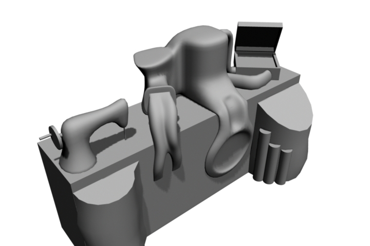
Ive been contemplating ways to incorporate more 'domestic' household items into the thingummybob. Today's experiment was a meat grinder. Although bringing back horrible memories of watching "The Wall" over and over again in highschool art class, I think it could work out pretty cool. It could give the actors another object to interact with as well. The "meat" cranked out of it could be pipes that grow and fade into the main box where they intertwine and create the machines underbelly. Just a thought.
I also reworked the 'lazy suzan' to better connect with the meat grinder. I've had to pay much more attention with this model to avoid messy geometry and overlapping in order to create a model that can be hopefully replicated by Matt when the time comes. We are still not sure if the wireless aspect will be stylized or if the actors will use one of the props, so i'm leaving it as is for now. Next step to finish sewing machine and figure out a way for it to attach to the grinder.

Friday, January 21, 2011
Monkey
Didn't make it to the production meeting today. I am going to Cleveland sat. so I needed the time today to work.
Spent 3.5 hours working on new monkey model. Just started placing in joints. Hopefully later this weekend I can upload a motion test video.
Spent 3.5 hours working on new monkey model. Just started placing in joints. Hopefully later this weekend I can upload a motion test video.
Thursday, January 20, 2011
Thursday Meeting with Actors 130-330pm
Worked for 2.5 hours on new Thingummybob model in maya. Met with Vita to discuss it before printing out a render and heading over to theater to meet with the actors. I flipped the sewing machine to the other side so the actors could use it properly. Also explored ideas for blurring the line between "top" and "bottom" of the thingummybob.

Spent 2 hours in class with the actors.
http://www.youtube.com/watch?v=WQfYUU4tvvE
We met with the actors today to discuss ideas for the Thingummybob scene and to watch the progress they have been making. The only object set in stone for the scene is the box center stage. Random props were used to take the place of the "objects to be built later" including a sewing machine, lazy susan, mechanical pump, wireless and a couple others. After watching the actors run throught the scene, it was decided that there needed to be six separate objects the actors would use to create the thingummybob. The wireless will most likely be already setup on the box from the scene prior and will also be the last object to be taken away. The first brought on will be sewing machine. Each women, while singing their parts will sit and work the sewin machine as the thingummybob comes together. I imagine as they use the sewing machine, it will produce a ribbon that crawls across the surface of the box as the thingummybob is created as well as being the driving force behind the entire machine i.e. as the needle raises up and down the pump begins to work, pipes begin to form, gears begin to turn etc. Near the end of the song, the music stops and the men (soldiers) march across the scene from backstage, and take four items, one for each soldier, that the women had just created. The projection of the thingummy bob will wipe clean as the first soldier passes infront. At the end, the women are singing acapella and only the sewing maching and wireless are left. Finally, an actress takes away the sewing machine leaving a single actress to work at the wireless.
The actors expressed interest in making each of the four objects (besides the wireless and sewing machine) to represent some other aspect of domestic life. I'm not sure at this point what they could be. Maybe a meat grinder or some other mechanical type kitchen utensil or more gadgets pertaining to the production of textiles and clothing.
Tuesday, January 18, 2011
Meeting Jan 18th
Met with Nikki, Tom and Vita for about an hour. Mostly just an overview of where we are at and what we are to do next. I'm going to keep working on the thingummybob and also getting the rhesus monkey finished up by the end of the month.
Monday, January 17, 2011
Monkey Reworked
3.5 hours cleaning geometry/rigging and re-weighting
I thought I would take a break from the thingummybob until our meeting on Tuesday. I revisited the rhesus monkey model I made awhile ago. Ibson is coming to EMMA on the 28th to mocap for the monkey's movement, so it would be a good idea to get the model and rig closer to finished. I was happy with the model overall the first time around, but I made the mistake of modeling it in a pose not suitable for rigging and weighting (its on all fours, far from any kind of T pose). Before creating a whole new model, I spent a few hours adjusting geometry, mostly shapes and size of legs, in an attempt to make a more rig friendly model. It seemed no matte how much I cheated the model, I couldn't find a setup that allowed any kind of natural movement.
I thought I would take a break from the thingummybob until our meeting on Tuesday. I revisited the rhesus monkey model I made awhile ago. Ibson is coming to EMMA on the 28th to mocap for the monkey's movement, so it would be a good idea to get the model and rig closer to finished. I was happy with the model overall the first time around, but I made the mistake of modeling it in a pose not suitable for rigging and weighting (its on all fours, far from any kind of T pose). Before creating a whole new model, I spent a few hours adjusting geometry, mostly shapes and size of legs, in an attempt to make a more rig friendly model. It seemed no matte how much I cheated the model, I couldn't find a setup that allowed any kind of natural movement.
Friday, January 14, 2011
Thingummy Bob
Based on my final sketch and from meeting with vita, I came up with the following model. Our biggest research question/ interest is projecting onto organic/blob-ular surfaces so I tried to model the top half as one solid flowing piece while keeping shapes distinct enough to separate them visually. The far left model is the wireless. It's shape is based on the relief/perspective sculpture reference we looked at last week.

This render was to show ways the same model above, could be disassembled and moved around. It was roughly done and perhaps in to many pieces but serves more to get the basic idea of how these smaller objects can come together on the central box to from the thingummybob.

Vita suggested it would be a good idea to draw directly on top of one of the renders to represent 'projected' images. It worked out pretty well. Top from right to left: Sewing machine plugs into pipes/steampunk styled clock which connects to lazy suzan and then wireless. Middle: a conveyor belt formed from discharged bullet shells (from sewing machine) which flow right to left. Bottom right to left: Pump pulsing up and down with sewing machine. Guts/pipes of the machine projected. Furnace that powers the machine/reference to crematorium. Steam stacks and barrel that is catching the bullets as they fall from above.

Thursday, January 13, 2011
Thingummy Bob Sketches

I was trying to combine gears with a sort of 'domestic' living room table or something. Dropped it pretty early.

Here I was exploring forced perspective and trying to find a form that could represent a sewing machine.


Did some sketches on how the thingummy bob should look. It's surprisingly difficult to start designing something so obscure. I knew I wanted to include some surrealist ideas and M.C. Escher-esk designs (maybe in the pipes) and that the "thing" would be driven by a sewing machine. Other than that I just started drawing shapes and forms based on surrealist sculpture and tried to explore how the final product could be broken down and pieced back together.
Tuesday, January 11, 2011
Meeting Jan. 11th
Went over thing-umma-bob sketches and 3d models from the week before. We sat down as a group (Vita, Nikki, Tom and I) and started sketching out ideas on the white board. It was nice to bounce idea's back and forth and we came up with some pretty good ideas to go off of. The final machine will most likely be powered by the sewing machine, which will drive the motion somewhat like the game mouse trap. Gears, pipes, steam, conveyor etc. will all make up the "thing". We also discussed Nikki's Noor poem story ideas and general aspects of stage and projector layout.

Sunday, January 9, 2011
Wrapping up projection excersice
There were many things to learn from this projection exercise. First off, Ben's camera/projector system for calculating object and camera positions in physical and digital space worked excellent. Secondly, Nikki and I were reminded of the importance of checking and double checking projector settings. When we began working on the 2d portion, we neglected to check our keystone values on the Optoma. We would have noticed earlier if we were projecting in 3d when our camera's didn't align, but since we were drawing live in photoshop we unknowingly adjusted for the keystoned projection. When I got to projecting 3D, we noticed the problem so it was necessary to move the duck and sphere to match the projection, so we decided to first wrap up 2D before moving on so that we wouldn't have to move objects back and forth.
The first thing I did before beginning building objects in maya was figuring out the their physical dimensions. It was an easy process. The duck was built from a previous 3D model I have made so it was just a matter of scaling the model to match. The sphere we wrapped with a string to find its circumference and did the easy math. Since the objects are organic, there was no easy way to measure their position in physical compared to its surroundings, (back wall). If it were a cube we could just measure from a corner and match it exactly in maya. I ended up attempting to find a center point on both the sphere and the duck and making an estimate of there positions. With Bens new system of calculating camera positions/settings, I knew that our 3D camera was correct so it was just a matter of projecting the 3D image and nudging the physical objects into place. Once everything aligned I could place tape on the table to help realign the objects if we had to move them.
After everything was aligned it was just a matter of creating the animations in maya to explore lighting and geometry deformation. I stared with lighting. I created a mallard texture to project onto the duck and a basketball for the sphere. I created a light pointing at the objects from the right rear. I animated it to move clockwise around the objects so that we could see how the shadows looked in the physical space. The shadows translated well and without deformations that relied on perspective, it was viewable from a wide range of angles.
For the next part of the exercise I extruded a series of squares from both the duck and sphere. Initially I animated random squares extending to random distances. It seemed like a good idea, but when watching the animation play as projection it became distracting and too difficult to analyze. So I reworked the maya file and made everything much more uniform. The squares were all extruded 'every other' and I made sure to extrude them together. I also slowed the animation down so we could see how the extrusions worked at many distance. I began with pulling them inwards and then slowly extruding them outwards. As expected, the shorter the distance, whether pulling in or pushing out, the wider viewing angle to view to illusion properly. As the squares traveled further outward towards the viewer, the illusion of depth was lost unless you stood very close to the projection source. The "intrusion" of squares were much more effective from a range of viewing angles when pulled in to greater depths.
We also learned a very valuable lesson about projection surfaces. The sphere was made of foam, and something about it's pouruss and reflective material dulled all of the projections. Also, purely white materials tend to over saturate the projections as well so you have to either a.) adjust the animations color balance or b.) paint the physical objects a slightly darker shade of gray. White semi-glossy posterboard was used for the floor and back walls. The surfaces caused a lot of light bounce which washed out the lower parts of the projections even when projecting black.
The first thing I did before beginning building objects in maya was figuring out the their physical dimensions. It was an easy process. The duck was built from a previous 3D model I have made so it was just a matter of scaling the model to match. The sphere we wrapped with a string to find its circumference and did the easy math. Since the objects are organic, there was no easy way to measure their position in physical compared to its surroundings, (back wall). If it were a cube we could just measure from a corner and match it exactly in maya. I ended up attempting to find a center point on both the sphere and the duck and making an estimate of there positions. With Bens new system of calculating camera positions/settings, I knew that our 3D camera was correct so it was just a matter of projecting the 3D image and nudging the physical objects into place. Once everything aligned I could place tape on the table to help realign the objects if we had to move them.
After everything was aligned it was just a matter of creating the animations in maya to explore lighting and geometry deformation. I stared with lighting. I created a mallard texture to project onto the duck and a basketball for the sphere. I created a light pointing at the objects from the right rear. I animated it to move clockwise around the objects so that we could see how the shadows looked in the physical space. The shadows translated well and without deformations that relied on perspective, it was viewable from a wide range of angles.
For the next part of the exercise I extruded a series of squares from both the duck and sphere. Initially I animated random squares extending to random distances. It seemed like a good idea, but when watching the animation play as projection it became distracting and too difficult to analyze. So I reworked the maya file and made everything much more uniform. The squares were all extruded 'every other' and I made sure to extrude them together. I also slowed the animation down so we could see how the extrusions worked at many distance. I began with pulling them inwards and then slowly extruding them outwards. As expected, the shorter the distance, whether pulling in or pushing out, the wider viewing angle to view to illusion properly. As the squares traveled further outward towards the viewer, the illusion of depth was lost unless you stood very close to the projection source. The "intrusion" of squares were much more effective from a range of viewing angles when pulled in to greater depths.
We also learned a very valuable lesson about projection surfaces. The sphere was made of foam, and something about it's pouruss and reflective material dulled all of the projections. Also, purely white materials tend to over saturate the projections as well so you have to either a.) adjust the animations color balance or b.) paint the physical objects a slightly darker shade of gray. White semi-glossy posterboard was used for the floor and back walls. The surfaces caused a lot of light bounce which washed out the lower parts of the projections even when projecting black.
Taken from extreme left of projection source.

Same as above but with more extreme extrusion. Notice how quickly the illusion is lost.

Close up and to the left....

Table height and extreme right.

Straight on and short deformation


Straight on with lengthier deformation. Most of the illusion stays intact from this view.

Saturday, January 8, 2011
Thing Ummy Bob brainstorm session 1-6-11
Today I met Vita and Nikki over at the drake to work with the actors in Thing Ummy Bob development. (about 2 hours) We listened to the song a couple times then had a brainstorm session with possible performance ideas and object designs. It was interesting to here what the actors bounce ideas off each other in such quick succession. Some of the major points taken away from the session were:
-Contrasting beautiful women with work environment
-"cute song" contrasted with dirty/gritty labor
-Slow build of structure-one object at a time changing projections with each addition
-The idea of not knowing what your making but being enthusiastic about it "we're going to win the war!"
-Music created by motion
-Possibly building the thing ummy bob out of objects women are "supposed" to be familiar with (ex. sewing machines)
-Possibly ending with a surreal steam punk type mechanical object.
Time to start sketching.
-Contrasting beautiful women with work environment
-"cute song" contrasted with dirty/gritty labor
-Slow build of structure-one object at a time changing projections with each addition
-The idea of not knowing what your making but being enthusiastic about it "we're going to win the war!"
-Music created by motion
-Possibly building the thing ummy bob out of objects women are "supposed" to be familiar with (ex. sewing machines)
-Possibly ending with a surreal steam punk type mechanical object.
Time to start sketching.
Tuesday, January 4, 2011
Meeting Jan. 4th
Met with Vita, Nikki and Tom today for about 2 hours. Discussed updates on script developement from theater folks. It's been decided that there is going to be a musical number in the show. The actors will be performing the Arthur Askey version of Thing-ummy-bob (Thats gonna win the war). Its a song about women in the war and their role of manufacturing the thing that will win the war. The song is completely un-specific and gives me us a chance as designers/artists to design the object from the ground up. It is my next assignment to start sketching out possible designs.
Monday, December 13, 2010
Projection Mapping Excercises
Sunday 3-730 and Monday 2-630 and Tuesday 2-330 (meeting with Matt)
Nikki and I started running through Matt's projection exercise instructions. Took a little time to set up projector, duck, ball etc. then mostly worked on painting dots and stripes onto the environment. Painting on the objects can be very disorienting. The ground plane is closest to perp. with the projector so small adjustments make for big results. Same goes for the edges of the sphere and duck, when you get to the boarder of what the projector sees the images become more skewed.
After continuing to draw on Monday, I decided to start setting up our Maya scene for projection. I took rough estimates of distances for now until we are done with the photo shop phase and can touch and move the objects to get better measurements. Part one of the 3d experiments is going to be a problem. I'm supposed to apply a texture with a series of spheres all of the same size cover the objects. I cant properly project/edit uv's to give a uniformed pattern. The other two steps, animating lights/shadows and "intrusion"/extrusion are blocked and ready to go.
Nikki and I started running through Matt's projection exercise instructions. Took a little time to set up projector, duck, ball etc. then mostly worked on painting dots and stripes onto the environment. Painting on the objects can be very disorienting. The ground plane is closest to perp. with the projector so small adjustments make for big results. Same goes for the edges of the sphere and duck, when you get to the boarder of what the projector sees the images become more skewed.
After continuing to draw on Monday, I decided to start setting up our Maya scene for projection. I took rough estimates of distances for now until we are done with the photo shop phase and can touch and move the objects to get better measurements. Part one of the 3d experiments is going to be a problem. I'm supposed to apply a texture with a series of spheres all of the same size cover the objects. I cant properly project/edit uv's to give a uniformed pattern. The other two steps, animating lights/shadows and "intrusion"/extrusion are blocked and ready to go.
Adventures in Camoland
I made contributions in several areas for this project beside conceptual development. I was in charge of building, lighting, texturing, animating and rendering the environments that were to be projected. Jon helped me out a lot with the rendering on the render farm. I was the only one in the group with projection mapping experience (to start of with anyway) so getting the physical spaces to match the virtual was my job. Also I worked with Ben to calculate specs. on the Sanyo projector (we already had numbers for the cannon) so that we could align it correctly in the physical space as well as properly replicating the virtual world to match the physical. Jon and I spent a lot of time exploring how to project onto 3 faces of a geometrical object from a projector location distant from the audiences point of view. I also set up, lit and shot (along wit Jon) the EMMA space for green screening as well as post production work to combine the footage and our animation. Jon and I also spent time in post doing audio and timing our animations to align with actor performances.
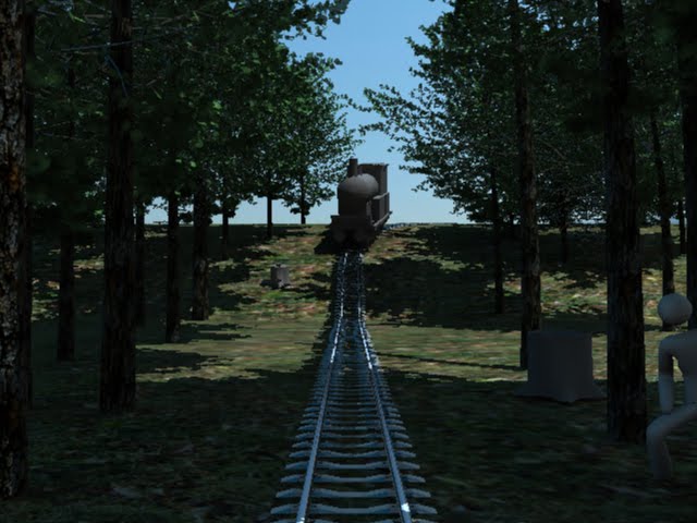
Alex, Jon and myself were assigned group one : camouflage training for this assignment. We wanted to treat the stage/props like a blank canvas. Something that we could paint with light and projection but keep a believable environment for the actors to perform in and with. Before meeting with the Ibsen, Tori, Alex, Aaron, and Ashley, we discussed several camouflage techniques and at some point found a period camouflage lookout that was shaped like a tree trunk. We decided to create a forest environment for out actors to perform in. Later we added a train and tracks to the piece as a starting point of action. It gave the actors a reason for being in the environment (sabotaging the train while going through a mock training session). The script changed very little from day one. The "classroom" scene was a little harder to figure out. We decided in the end to go with a bunker type setting so that when the forest turned into it we would keep continuity with "in the field training".
We found that when projecting onto 3 faces from a "non viewer" angle that no adjustments need to be made to projector configuration, but the process for rendering in maya does. As long as you pick a point of origin in the physical space and measure from there to your objects and projector (and matchin those measurements in maya) that projections would still align. The trouble came when trying to figure out how to compensate for the perspective difference from audience to a projector 16 feet of the ground.
We found that an extra camera was needed to correctly project from maya. We added a camera from the audiences point of view, or at least a rough estimate. We rendered from that camera, saved it as a texture material, and projected it back onto the objects from our "projector" camera. When viewed from the audience camera the texture should hypothetically create the illusion of forced perspective. I say hypothetically because properly projecting the textures is a lot harder than expected. I had to do a lot of UV tweaking. There must be a better way and definitely something we need to discover. I also learned that when rendering the texture for projection, using 2048x1536 resulted in a much higher quality render even though we rendered at 1024x768 in the end.
I wanted to create an environment that felt like more than just projections and to extend the space. I tossed out the idea of green screening one of the actors to insert them in the physical space and everyone was on board. Alex, Jon and I met over in EMMA where we set up the green screen and Alex gave us some instructions on how to light it. Later on that week we met with actress Tori, she volunteered for our experiment, to shoot the footage. When lighting the screen we basically just tried to flatten the background as much as possible and eliminate unwanted shadows. After shooting Jon and I brought the footage into After Effects where it was fairly simple to rough out the screen. We also got pretty lucky with how Tori fit into the digital space. Initially, she did not walk far enough to get to the train tracks, lucky for us we just moved them closer and it fit perfect. With a little color matching and use of a matte choker we had her in the virtual space and acting. In the end it probably gave the actors the most grief because they had to act with a video whom could not respond to and sometimes even see.
Our group put some real time in last weekend in order to pull the show together. Even though we had solidified ideas and environments, technical difficulties always slow you down. The following is Jons account of 9 hours of Friday activities.
Friday December 3 - attempted to align 3D projection maps to physical objects on stage (2
boxes), took measurements using measuring tape, dimensions of object, distance of object to
projector, height of projector relative to object, Jeremy used method from Camouflage Project
to align and project onto physical objects
- difficulty measuring the angle (vertical tilt) of the camera in the physical space, difficulty
measuring precise distances from object to camera and height of camera using measuring tape,
need a more precise tool or a more precise method to measure at these distances in complex
environments
- test object (larger box lying length wise, horizontally on the right side of stage), marked and in
its final position
- in Maya, test used cube with a simple red shader as the projected object, dimensions of
physical object and other measurements entered into Maya project
- difficulty aligning projected objects with physical objects using method from Camouflage
Project, projected objects weren't oriented properly, seemingly wrong angles and distance to
camera, vertical tilt of camera also seemed off
- test object moved in physical space so front face sat head on relative to camera view,
perpendicular to camera, instead of the angle set for final position, rotated against marked
focal point (lower left front facing corner of object), this was done in an attempt to ease the
process of alignment, object in Maya reconfigured accordingly
- new measurements taken, entered into Maya project
- fail, projection map still off, seemed to make no difference, speculated either the resolution,
aspect ratio, or some other lens setting of projector was to blame
- resolution of projector correct (1024 x 768), apparently the projector is supposed to auto
detect proper resolution and aspect ratio from computer at default, so default settings were
reapplied to projector
- fail, projection map still off, seemed to make no difference
- began deviating from exact measurements, tweaking numbers in an attempt to align
projected object, sporadic success, some changes got us closer to alignment while others undid
any perceivable progress, took 1 step forward and two steps back, at this point we may have
been going in circles
- contacted Ben for assistance, reverted to measurements and ran through the Camouflage
procedure again, still ran into a similar problem with alignment, proportions of projected object
seemed off, front face too large and top face too narrow
- made attempts to raise the height of the camera in Maya project and adjust the angle
(vertical tilt) accordingly, attempt to fix issue with front and top proportions
- mixed results, seemed as though every time an issue with front or top face was resolved
something else would fall out of alignment
- determined that the height of the camera relative to the distance from the focal point of
the object needed adjustment, as opposed to changing only the height of the camera then
adjusting the angle accordingly
- attempted to use focal point (lower left front facing corner of object), as a rotation point for
camera in Maya project, allowing us to adjust the "height of the camera relative to the distance
from the focal point of the object"
- success, but only to a certain extent, after about an hour of messing around with this method
we were able to achieve a nearly acceptable alignment, the problem involved the right side or
outer edge of the test object, it was skewed at an odd angle while every other edge was aligned
properly, inexplicable and couldn't be solved with the 'focal point rotation' method
- suspected that either the lens of the projector or the camera settings in Maya were to blame
- scheduled meeting with Ben around noon the next day
We gave up for the night after getting now where. After meeting with Ben the next day, we discovered that since our projector was hung upside down, we needed to flip our film offset to negative and like magic it aligned almost perfectly.
We spent the next 14 hours sat. building and lighting our finalized virtual sets.
Sunday we managed to spend 30+ hours in an attempt to wrap up by monday. We got everything but sound which Jon and I finished on Tuesday. Jon did most of it however, I was still out of it, but I was good backup.
Tree Textures


Textures Projected back onto geometry


Physical Objects Projected On

Wall Projections

FINAL FOREST

FINAL CLASS

Shots While Working and From Show
 Forest Performance
 Tori Green Screened
 Blank Canvas

Jon Enjoying the Green Screen

Projection Testing

I had a great group, Jon, Alex, Ibsen, Tori, Alex, Aaron, and Ashley.. We all worked together great and everyone was open to change and adaptation to make this project work. Lots of long hours paid off.
Alex, Jon and myself were assigned group one : camouflage training for this assignment. We wanted to treat the stage/props like a blank canvas. Something that we could paint with light and projection but keep a believable environment for the actors to perform in and with. Before meeting with the Ibsen, Tori, Alex, Aaron, and Ashley, we discussed several camouflage techniques and at some point found a period camouflage lookout that was shaped like a tree trunk. We decided to create a forest environment for out actors to perform in. Later we added a train and tracks to the piece as a starting point of action. It gave the actors a reason for being in the environment (sabotaging the train while going through a mock training session). The script changed very little from day one. The "classroom" scene was a little harder to figure out. We decided in the end to go with a bunker type setting so that when the forest turned into it we would keep continuity with "in the field training".
We found that when projecting onto 3 faces from a "non viewer" angle that no adjustments need to be made to projector configuration, but the process for rendering in maya does. As long as you pick a point of origin in the physical space and measure from there to your objects and projector (and matchin those measurements in maya) that projections would still align. The trouble came when trying to figure out how to compensate for the perspective difference from audience to a projector 16 feet of the ground.
We found that an extra camera was needed to correctly project from maya. We added a camera from the audiences point of view, or at least a rough estimate. We rendered from that camera, saved it as a texture material, and projected it back onto the objects from our "projector" camera. When viewed from the audience camera the texture should hypothetically create the illusion of forced perspective. I say hypothetically because properly projecting the textures is a lot harder than expected. I had to do a lot of UV tweaking. There must be a better way and definitely something we need to discover. I also learned that when rendering the texture for projection, using 2048x1536 resulted in a much higher quality render even though we rendered at 1024x768 in the end.
I wanted to create an environment that felt like more than just projections and to extend the space. I tossed out the idea of green screening one of the actors to insert them in the physical space and everyone was on board. Alex, Jon and I met over in EMMA where we set up the green screen and Alex gave us some instructions on how to light it. Later on that week we met with actress Tori, she volunteered for our experiment, to shoot the footage. When lighting the screen we basically just tried to flatten the background as much as possible and eliminate unwanted shadows. After shooting Jon and I brought the footage into After Effects where it was fairly simple to rough out the screen. We also got pretty lucky with how Tori fit into the digital space. Initially, she did not walk far enough to get to the train tracks, lucky for us we just moved them closer and it fit perfect. With a little color matching and use of a matte choker we had her in the virtual space and acting. In the end it probably gave the actors the most grief because they had to act with a video whom could not respond to and sometimes even see.
Our group put some real time in last weekend in order to pull the show together. Even though we had solidified ideas and environments, technical difficulties always slow you down. The following is Jons account of 9 hours of Friday activities.
Friday December 3 - attempted to align 3D projection maps to physical objects on stage (2
boxes), took measurements using measuring tape, dimensions of object, distance of object to
projector, height of projector relative to object, Jeremy used method from Camouflage Project
to align and project onto physical objects
- difficulty measuring the angle (vertical tilt) of the camera in the physical space, difficulty
measuring precise distances from object to camera and height of camera using measuring tape,
need a more precise tool or a more precise method to measure at these distances in complex
environments
- test object (larger box lying length wise, horizontally on the right side of stage), marked and in
its final position
- in Maya, test used cube with a simple red shader as the projected object, dimensions of
physical object and other measurements entered into Maya project
- difficulty aligning projected objects with physical objects using method from Camouflage
Project, projected objects weren't oriented properly, seemingly wrong angles and distance to
camera, vertical tilt of camera also seemed off
- test object moved in physical space so front face sat head on relative to camera view,
perpendicular to camera, instead of the angle set for final position, rotated against marked
focal point (lower left front facing corner of object), this was done in an attempt to ease the
process of alignment, object in Maya reconfigured accordingly
- new measurements taken, entered into Maya project
- fail, projection map still off, seemed to make no difference, speculated either the resolution,
aspect ratio, or some other lens setting of projector was to blame
- resolution of projector correct (1024 x 768), apparently the projector is supposed to auto
detect proper resolution and aspect ratio from computer at default, so default settings were
reapplied to projector
- fail, projection map still off, seemed to make no difference
- began deviating from exact measurements, tweaking numbers in an attempt to align
projected object, sporadic success, some changes got us closer to alignment while others undid
any perceivable progress, took 1 step forward and two steps back, at this point we may have
been going in circles
- contacted Ben for assistance, reverted to measurements and ran through the Camouflage
procedure again, still ran into a similar problem with alignment, proportions of projected object
seemed off, front face too large and top face too narrow
- made attempts to raise the height of the camera in Maya project and adjust the angle
(vertical tilt) accordingly, attempt to fix issue with front and top proportions
- mixed results, seemed as though every time an issue with front or top face was resolved
something else would fall out of alignment
- determined that the height of the camera relative to the distance from the focal point of
the object needed adjustment, as opposed to changing only the height of the camera then
adjusting the angle accordingly
- attempted to use focal point (lower left front facing corner of object), as a rotation point for
camera in Maya project, allowing us to adjust the "height of the camera relative to the distance
from the focal point of the object"
- success, but only to a certain extent, after about an hour of messing around with this method
we were able to achieve a nearly acceptable alignment, the problem involved the right side or
outer edge of the test object, it was skewed at an odd angle while every other edge was aligned
properly, inexplicable and couldn't be solved with the 'focal point rotation' method
- suspected that either the lens of the projector or the camera settings in Maya were to blame
- scheduled meeting with Ben around noon the next day
We gave up for the night after getting now where. After meeting with Ben the next day, we discovered that since our projector was hung upside down, we needed to flip our film offset to negative and like magic it aligned almost perfectly.
We spent the next 14 hours sat. building and lighting our finalized virtual sets.
Sunday we managed to spend 30+ hours in an attempt to wrap up by monday. We got everything but sound which Jon and I finished on Tuesday. Jon did most of it however, I was still out of it, but I was good backup.
Tree Textures


Textures Projected back onto geometry


Physical Objects Projected On

Wall Projections
EARLY
FINAL FOREST

FINAL CLASS

Shots While Working and From Show
Bunker/Class Performance
 Forest Performance
 Tori Green Screened
 Blank Canvas
Jon Enjoying the Green Screen

Projection Testing

I had a great group, Jon, Alex, Ibsen, Tori, Alex, Aaron, and Ashley.. We all worked together great and everyone was open to change and adaptation to make this project work. Lots of long hours paid off.
Tuesday, November 16, 2010
Process For Projecting on Cube in EMMA
Step by step process
A.)-For this first test the Audience's view wasn't taken into much consideration, but it should. (in order to view the projection correctly you need to be at projector level which in this case was lying on the floor.)
B.)-Our next step was to measure and arrange our objects in physical space.
1.The object we were projecting onto was a rectangular box that measured 77.75"x30"x18".
2.The projector was, in this case, arbitrarily placed 147.5 " away from the center front face of the box which was enough distance project on the entire surface. When considering projector placement it should in general be as Matt wrote- as close as practical for maximum resolution and minimum background bleed. I also tried to place it perpendicular to the box. At this stage it is also important to either zoom all the way in or all the way out so that calculations down the road are easier to find.

C.)Modeling a Virtual "set" that matched the Physical one.
1.I chose a global origin of 0,15,0 so that the box could be at the center of the virtual space with the bottom face flush with the ground plane (translate Y=15 since the box would be 30 units high)
2. It is important to also pick your units of measure within maya. We measure the physical in inches so chose inches for maya.
3.I built a polygonal cube that matched the measurements of the physical cube 77.75x30x18 and placed it at the origin. I left rotations at o,o,o since we would be projecting on the object perpendicular from one side only (in order to calibrate our maya camera with the projector we started simple with the hopes the same measurements would work when the objects are angled).
4. Next I created a camera within maya. Using the measuring tool I placed it 147.5" away from the front edge and center of the box.
5. After the camera positions match in physical and virtual space, we needed match the camera's attributes with those of the porjector.
-Aspect Ratio: 4:3- The easiest. The projector was set to 4:3 so we did the same for the camera.
-Field of View: 35.48: Can be found hopefully in the manual, or what we did was project a perfect square onto a perpindicular surface. Measure the length from lens to center of projection then from center to edge of projection we could figure out the angle using the Pythagorean theorem. Multiply by two since we only calulated half the field of view. I'm also pretty sure that the Aperture setting directly affects/calculates field of view so finding that in the manual would also be idea.
-Aperture: .902-.678: So we had a lot of trouble figuring this number out at first. Through some rough mathematics and some other measurements we got a projection that lined up closely. We later found out that some of the confusion lied in somewhat different understanding of what aperture meant in Maya compared to the Projector. It turns out that for a projector, aperture is reffering to the the LCD panel size, which according to some sources is the diagonal of the aperture measurements. Using the value from the manual produced bad results in Maya, as before, but produced better results once we realized we had been using the wrong end of the focal length range.(Hence why it is important to zoom all the way in or out in the beginning).

At this point, with all of our measurements and camera/projector settings matching in both maya and in EMMA, we were able project onto our cube properly without manual tweaking and the render-re-render process.
We did a quick experiment with rotating the physical box and then matching that rotation for the virtual to see if our calculations would still be effective and they were.
The animations were secondary for the most part. Just wanted to test what kind of depth you could get inside such a small space. I didn't push it to the max but I think it was pretty successful overall.


1.I chose a global origin of 0,15,0 so that the box could be at the center of the virtual space with the bottom face flush with the ground plane (translate Y=15 since the box would be 30 units high)
2. It is important to also pick your units of measure within maya. We measure the physical in inches so chose inches for maya.
3.I built a polygonal cube that matched the measurements of the physical cube 77.75x30x18 and placed it at the origin. I left rotations at o,o,o since we would be projecting on the object perpendicular from one side only (in order to calibrate our maya camera with the projector we started simple with the hopes the same measurements would work when the objects are angled).
4. Next I created a camera within maya. Using the measuring tool I placed it 147.5" away from the front edge and center of the box.
5. After the camera positions match in physical and virtual space, we needed match the camera's attributes with those of the porjector.
-Aspect Ratio: 4:3- The easiest. The projector was set to 4:3 so we did the same for the camera.
-Field of View: 35.48: Can be found hopefully in the manual, or what we did was project a perfect square onto a perpindicular surface. Measure the length from lens to center of projection then from center to edge of projection we could figure out the angle using the Pythagorean theorem. Multiply by two since we only calulated half the field of view. I'm also pretty sure that the Aperture setting directly affects/calculates field of view so finding that in the manual would also be idea.
-Aperture: .902-.678: So we had a lot of trouble figuring this number out at first. Through some rough mathematics and some other measurements we got a projection that lined up closely. We later found out that some of the confusion lied in somewhat different understanding of what aperture meant in Maya compared to the Projector. It turns out that for a projector, aperture is reffering to the the LCD panel size, which according to some sources is the diagonal of the aperture measurements. Using the value from the manual produced bad results in Maya, as before, but produced better results once we realized we had been using the wrong end of the focal length range.(Hence why it is important to zoom all the way in or out in the beginning).

We did a quick experiment with rotating the physical box and then matching that rotation for the virtual to see if our calculations would still be effective and they were.
The animations were secondary for the most part. Just wanted to test what kind of depth you could get inside such a small space. I didn't push it to the max but I think it was pretty successful overall.


Projection Mapping Second pass WIP
In recent years, the art of 3D projection mapping has been climbing in popularity. According to Wikipedia, 3D projection mapping is defined as “any method of mapping three-dimensional points to a two-dimensional plane.” The most common form of this technique is the mapping of geometrical shapes and architectural facades. These 3D projections give artists the power “change” the objects surface and create illusions of depth, forced perspective as well as more dramatic special effects such as objects crumbling, morphing and turning into cloth. However before these artistic visualizations can be realized, you must understand how the mapping process works and that is what I have been researching in recent weeks.
Initially my knowledge of the projection process was very limited. I was not aware of the intricacies of process that were necessary for accurate projections. I was under the impression that if and object was accurately replicated in 3D software it was merely the act of matching the digital camera position with the projectors position in real space that would allow effective mapping. I soon learned that these notions were incorrect. While struggling to align our 3D rendered models with real world objects, we bypassed the process by manipulating geometries to make up for our miscalculations. However, we soon realized that while this may work for static projections, animation would likely expose the flaws in our process.
Creating an accurate and intuitive method for mapping these projections became imperative and Matt, Ben and I began experimenting. We decided to start simple by projecting onto a single flat surface in the hopes that what we discovered could translate into more complicated perspective projections. The first step was accurately measuring our rectangular box: 77.75w x 30”h x 18”d. With these measurements we were able to create a replica within Maya. The next step was to translate the distance between real-world projector and object to our digital camera and 3D object. The projector was placed perpendicular to the box and at a distance of 144.5 inches measured from lens to the box’s projector facing side. The virtual box’s position in was coordinates (xyz) 0,15,0. Since the box is 30 inches high chose its Y position 15 inches above the ground plane which put the box’s bottom flush with the floor. The camera was created and placed 144.5 in. away from the virtual box facing side which would put it 154.5 in. away from the 0,0,0 origin. The physical projector lens was measured 3.25 inches off the ground so we also bumped the digital camera up 3.5 in. in the Y direction.
After figuring the spatial relationships in physical and digital space it was necessary to adjust the digital camera’s Focal Length, Angle of View, Aperture Settings etc. to match that of our projector. These settings are projector specific and in this case we were using a Canon ______. The angle of view was calculated by projecting onto a close, perpendicular service so that the projection was square. We measured first the distance from projector lens to the center of the projection to get the adjacent side (X). Then we measured the width of the projector and divided it by two to get our opposite side (Y). Using the Pythagorean theorem we found the Hypotenuse (H). The tan ø =y/x, or our FOV angle =2* arctan (y/x).
The focal length was actually found in the Canon Owners manual which was 34.5. I believe that only one of these numbers needs to be found because their values directly correlate to one another. We used the found focal length since it was the most accurate and plugged it into our digital camera’s focal length value. However, manuals usually give you a focal length range to account for the zoom settings of the projector. We assumed that since we were zoomed all the way in, we would use the larger focal length. We discovered later that it was the smaller of the two numbers we should have used.
Initially my knowledge of the projection process was very limited. I was not aware of the intricacies of process that were necessary for accurate projections. I was under the impression that if and object was accurately replicated in 3D software it was merely the act of matching the digital camera position with the projectors position in real space that would allow effective mapping. I soon learned that these notions were incorrect. While struggling to align our 3D rendered models with real world objects, we bypassed the process by manipulating geometries to make up for our miscalculations. However, we soon realized that while this may work for static projections, animation would likely expose the flaws in our process.
Creating an accurate and intuitive method for mapping these projections became imperative and Matt, Ben and I began experimenting. We decided to start simple by projecting onto a single flat surface in the hopes that what we discovered could translate into more complicated perspective projections. The first step was accurately measuring our rectangular box: 77.75w x 30”h x 18”d. With these measurements we were able to create a replica within Maya. The next step was to translate the distance between real-world projector and object to our digital camera and 3D object. The projector was placed perpendicular to the box and at a distance of 144.5 inches measured from lens to the box’s projector facing side. The virtual box’s position in was coordinates (xyz) 0,15,0. Since the box is 30 inches high chose its Y position 15 inches above the ground plane which put the box’s bottom flush with the floor. The camera was created and placed 144.5 in. away from the virtual box facing side which would put it 154.5 in. away from the 0,0,0 origin. The physical projector lens was measured 3.25 inches off the ground so we also bumped the digital camera up 3.5 in. in the Y direction.
After figuring the spatial relationships in physical and digital space it was necessary to adjust the digital camera’s Focal Length, Angle of View, Aperture Settings etc. to match that of our projector. These settings are projector specific and in this case we were using a Canon ______. The angle of view was calculated by projecting onto a close, perpendicular service so that the projection was square. We measured first the distance from projector lens to the center of the projection to get the adjacent side (X). Then we measured the width of the projector and divided it by two to get our opposite side (Y). Using the Pythagorean theorem we found the Hypotenuse (H). The tan ø =y/x, or our FOV angle =2* arctan (y/x).
The focal length was actually found in the Canon Owners manual which was 34.5. I believe that only one of these numbers needs to be found because their values directly correlate to one another. We used the found focal length since it was the most accurate and plugged it into our digital camera’s focal length value. However, manuals usually give you a focal length range to account for the zoom settings of the projector. We assumed that since we were zoomed all the way in, we would use the larger focal length. We discovered later that it was the smaller of the two numbers we should have used.
Thursday, November 4, 2010
Learning to Align
So amidst all of our experiments and conceptual designs, properly aligning 3d objects within maya with there real world counterparts has been an arduous process. It goes something like this, Rotate, tweak, rotate, tweak, forever and ever until it is close. There is also the painstaking process of rendering out stills so we can full screen them and see if they align. Basically a long long process. Matt and Ben recently created a jitter patch/program that would allow us to isolate only our renderable area from maya and full screen it through the projector for real time alignment. As nice as it is, we still need to figure out how to accurately align camera/projector settings. Matt, Ben and I spent a few hours yesterday trying to figure this stuff out.
The scene we set up was simple. We decided to calculate a straight on projection to begin with so we only had to worry about a single face. I measured our physical box and created an accurate replica in maya.
1.77.75" wide, 30" high and 18"deep
2.Then we measured the distance from the projector lens to the box so we could properly position the digital camera.
3.Either measure the projectors angle of view or find out its focal length via. manual (AOV and FL seem to adjust to each other)
4.Make sure digital camera's resolution and film aspect ration match the projector settings. We used 1024x768 and 1.33 or 4:3.
5.The sketchiest part for me at this point is the camera aperture. I/we need to further understand what it is and what it controls. It seems to affect multiple settings in maya and needs to be adjusted accordingly. We could not find the projectors aperture setting so we found a formula online and used it to figure it out. This was much more Ben's area than mine and I still do not fully understand the process.
We came very close to aligning the box/projection yesterday. There are so many working factors that a small error in a single step could account for our miscalculations. Or there is another aspect we haven't found yet that is the culprit.


The scene we set up was simple. We decided to calculate a straight on projection to begin with so we only had to worry about a single face. I measured our physical box and created an accurate replica in maya.
1.77.75" wide, 30" high and 18"deep
2.Then we measured the distance from the projector lens to the box so we could properly position the digital camera.
3.Either measure the projectors angle of view or find out its focal length via. manual (AOV and FL seem to adjust to each other)
4.Make sure digital camera's resolution and film aspect ration match the projector settings. We used 1024x768 and 1.33 or 4:3.
5.The sketchiest part for me at this point is the camera aperture. I/we need to further understand what it is and what it controls. It seems to affect multiple settings in maya and needs to be adjusted accordingly. We could not find the projectors aperture setting so we found a formula online and used it to figure it out. This was much more Ben's area than mine and I still do not fully understand the process.
We came very close to aligning the box/projection yesterday. There are so many working factors that a small error in a single step could account for our miscalculations. Or there is another aspect we haven't found yet that is the culprit.


Subscribe to:
Posts (Atom)